Prime Movers Guide
for the Red Seal Millwright Exam
Internal combustion engines, electric motors, hydraulic motors, and gas turbines explained for the Red Seal Millwright exam — operation, maintenance, and troubleshooting for millwrights.
What Is a Prime Mover?
A prime mover is any machine that converts a natural energy source into mechanical work. It is the driver — the source of power that turns a shaft, which then drives a pump, compressor, conveyor, or any other piece of driven equipment. Every mechanical system a millwright works on has a prime mover at its heart.
Understanding prime movers is fundamental to millwright work — not at the level of an engine mechanic or power engineer, but at the level required to install, align, maintain, and troubleshoot the complete drivetrain from the energy source to the driven equipment.
Electric Motors as Prime Movers
The electric motor is the most common prime mover in industrial facilities. Covered in depth in the Electrical Fundamentals Guide — key points from a prime mover perspective:
Advantages as a prime mover:
- Simple, reliable, low maintenance compared to combustion engines
- Precise speed control with VFD
- No local emissions — clean for indoor use
- Instantly reversible (direction change by phase swap)
- Wide range of sizes — fractional horsepower to thousands of kilowatts
Limitations:
- Requires electrical infrastructure — not suitable for remote locations without power
- Vulnerable to power outages — no electricity, no drive
- High starting current unless soft starter or VFD is used
Millwright considerations:
- Correct coupling selection and alignment is critical — electric motors transmit torque cleanly with no vibration masking from combustion
- Motor nameplate must be verified against supply voltage and frequency before connection
- Rotation direction must be verified before connecting to driven equipment — reverse rotation can damage pumps, compressors, and fans immediately
Internal Combustion Engines
Internal combustion (IC) engines convert the chemical energy of fuel into mechanical work through controlled combustion inside a cylinder. Millwrights encounter IC engines as prime movers for generators, compressors, pumps, and mobile equipment.
Four-Stroke Cycle (Otto Cycle — Gasoline/Gas)
The four-stroke cycle is the operating principle of most gasoline and natural gas engines:
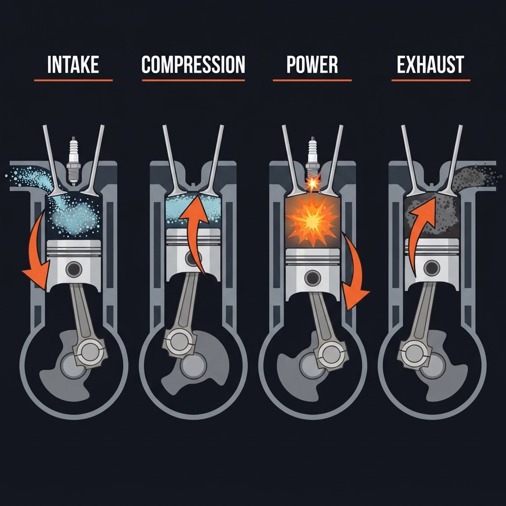
Intake
The piston moves downward, the intake valve opens, and the air-fuel mixture is drawn into the cylinder.
Compression
Both valves close. The piston moves upward, compressing the air-fuel mixture. Compression heats the mixture and prepares it for ignition.
Power (Combustion)
Near the top of the compression stroke, the spark plug fires. The burning mixture expands rapidly, driving the piston downward with force. This is the only stroke that produces work.
Exhaust
The exhaust valve opens. The piston moves upward, pushing burned gases out of the cylinder.
Firing order
In multi-cylinder engines, cylinders fire in a specific sequence to balance forces and smooth power delivery. The firing order is stamped on the engine block or found in service documentation.
EXAM TIP
Only one of the four strokes produces power — the power stroke. The other three strokes are driven by the flywheel's stored rotational energy and the power from other cylinders in a multi-cylinder engine.
Four-Stroke Diesel Cycle
The diesel cycle follows the same four strokes as the Otto cycle with one critical difference — there is no spark plug. The diesel engine relies on compression ignition.
Key difference
Diesel engines compress only air on the compression stroke — no fuel is present. The compression ratio is much higher than a gasoline engine (typically 16:1 to 23:1 vs. 8:1 to 12:1 for gasoline). At this compression ratio, the air temperature exceeds the autoignition temperature of diesel fuel. Fuel is injected at the top of the compression stroke and ignites spontaneously on contact with the hot compressed air.
Advantages of diesel
- Higher thermal efficiency than gasoline engines — more work extracted per unit of fuel
- No ignition system to maintain — no spark plugs, no ignition timing
- Diesel fuel is less volatile than gasoline — lower fire risk
- Higher torque at lower RPM — better suited for heavy-duty, low-speed applications
Disadvantages
- Higher compression requires heavier, more robust engine construction
- Cold starting is more difficult — glow plugs preheat the combustion chamber in cold weather
- Higher initial cost
Two-Stroke Cycle
Two-stroke engines complete a full power cycle in one revolution of the crankshaft — intake and exhaust happen simultaneously during the piston's travel, not in dedicated strokes.
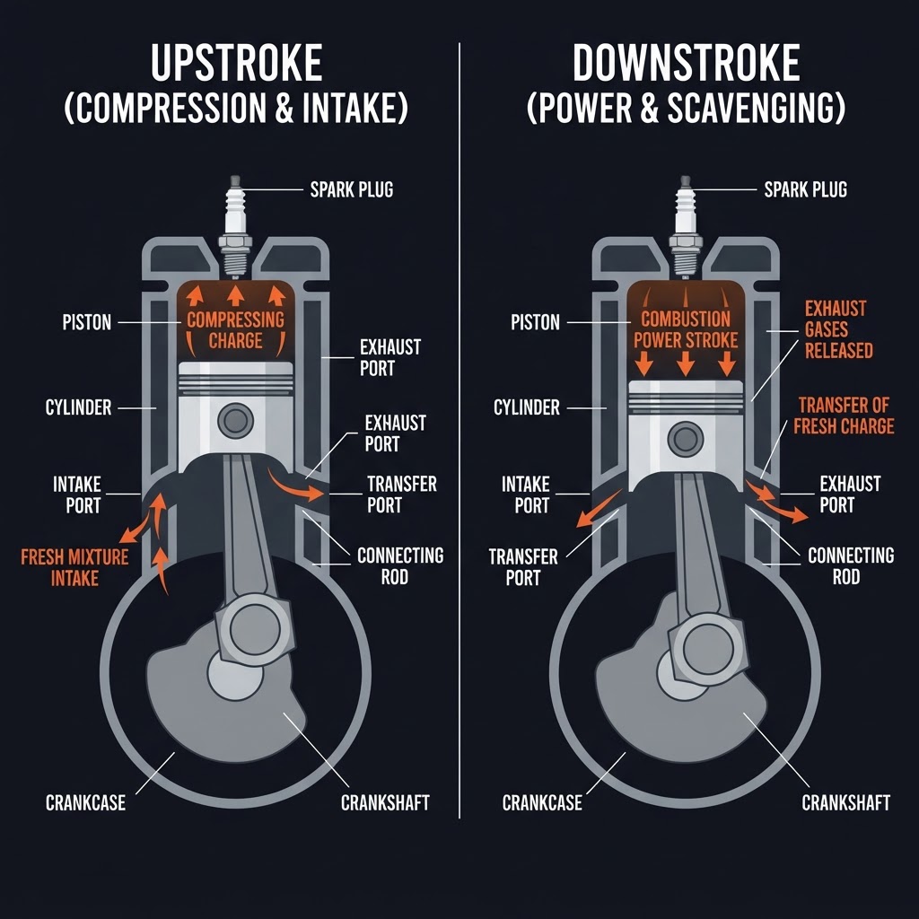
How it works:
- As the piston moves upward, it compresses the charge above it (compression stroke) while simultaneously creating a low-pressure area below that draws fresh charge into the crankcase
- At top of stroke, ignition occurs and the piston is driven downward (power stroke)
- Near the bottom of the stroke, exhaust ports are uncovered, allowing burned gases to escape, followed by intake ports that allow fresh charge to enter from the crankcase
Advantages
- Higher power-to-weight ratio
- Simpler construction — fewer moving parts, no valves
Disadvantages
- Less fuel efficient
- Higher emissions
- Oil must be mixed with fuel in some designs (total loss lubrication)
Applications
Small engines, chainsaws, some marine engines, older industrial equipment.
Engine Components Millwrights Work With
Flywheel
A heavy rotating disc attached to the crankshaft that stores rotational energy during the power stroke and releases it to drive the non-power strokes. Also serves as the connection point for the driven equipment — clutches, couplings, and ring gears are typically mounted to or machined into the flywheel.
Crankshaft
Converts the reciprocating (linear) motion of the pistons into rotational motion. Runs in plain bearings (main bearings) in the engine block. Crankshaft condition — journal wear, scoring, and alignment — is a major overhaul consideration.
Connecting rod
Connects the piston to the crankshaft journal. The small end connects to the piston pin (wrist pin); the big end connects to the crankshaft journal via a split bearing (rod bearing).
Camshaft
Controls valve timing. Driven by the crankshaft at half engine speed (one camshaft revolution per two crankshaft revolutions in a four-stroke engine). Cam lobes lift the intake and exhaust valves in the correct sequence.
Valvetrain
The system of components (camshaft, lifters, pushrods, rocker arms, and valves) that opens and closes the intake and exhaust valves. Valve clearance (lash) must be set to specification — too tight and valves do not fully close (burning), too loose and valves open late and close early (loss of power, noise).
Valve clearance (lash):
- Set with the engine cold unless otherwise specified
- Measured with a feeler gauge between the rocker arm and valve stem
- Different clearance specifications for intake and exhaust valves — exhaust valves run hotter and require more clearance
EXAM TIP
Valve clearance is measured and set with a feeler gauge. If an engine is noisy at the valve cover area, insufficient valve clearance is a primary suspect. Verify the specification — intake and exhaust clearances are often different.
Engine Lubrication
IC engines use a pressure lubrication system — an oil pump circulates oil under pressure to all critical bearing surfaces.
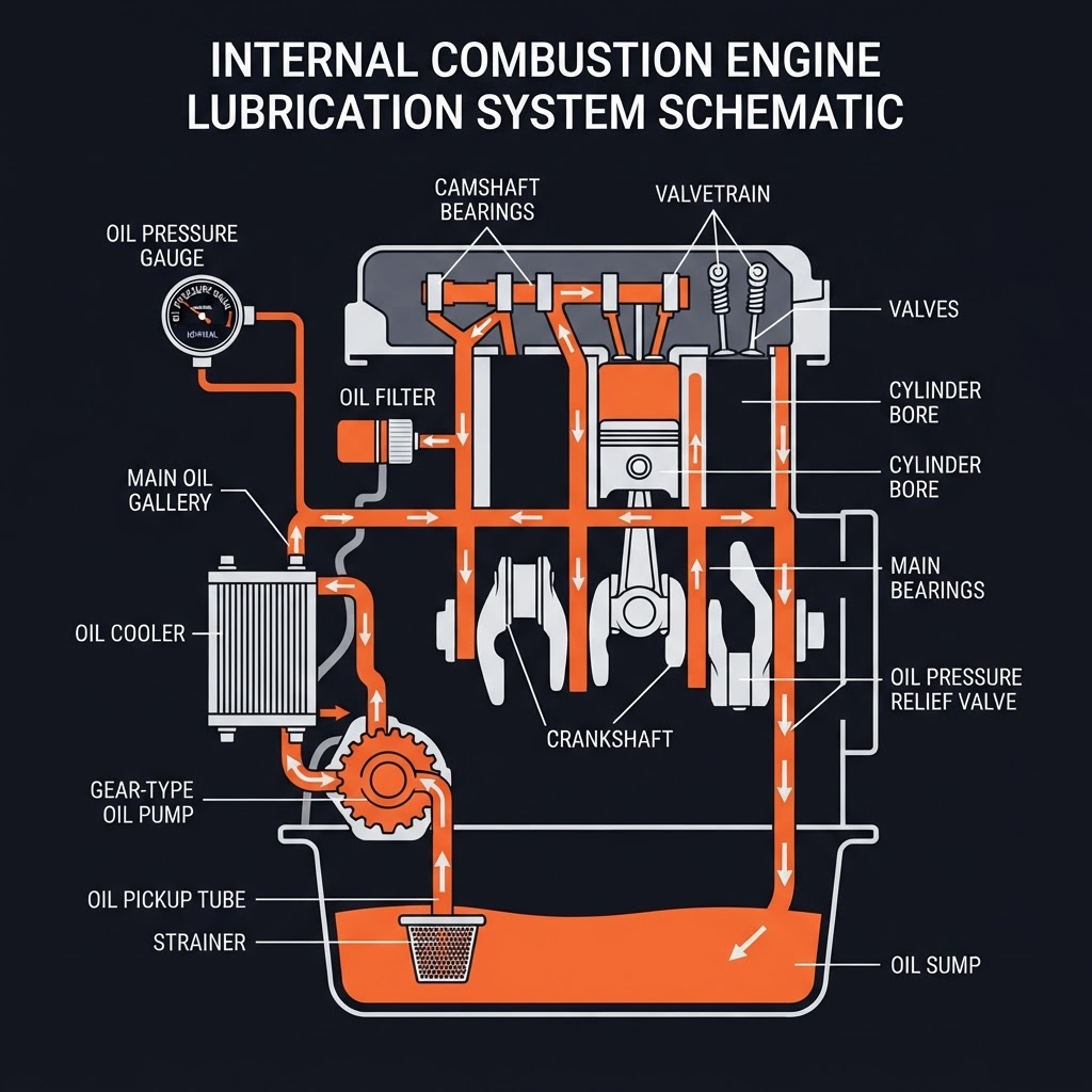
Oil pump
Typically gear-driven from the crankshaft. Draws oil from the sump through a strainer and delivers it under pressure to the main gallery.
Oil pressure
A critical operating parameter. Low oil pressure indicates worn bearings (excessive clearance allows oil to drain away), a failing oil pump, low oil level, or a blocked oil passage. An engine must be shut down immediately on low oil pressure indication — continued operation causes rapid bearing failure.
Oil galleries
Passages drilled through the block and heads that route pressurized oil to main bearings, rod bearings, camshaft bearings, and the valvetrain.
Oil cooler
In high-output engines, engine oil passes through a cooler (air or water-cooled) to maintain oil temperature within the operating range. Oil that is too hot loses viscosity and film strength.
EXAM TIP
Low oil pressure is a shutdown condition — not a warning to watch. An engine that continues to run on low oil pressure will fail its bearings in minutes. The millwright's responsibility is to shut down and investigate, not to continue operating and monitor.
Engine Cooling Systems
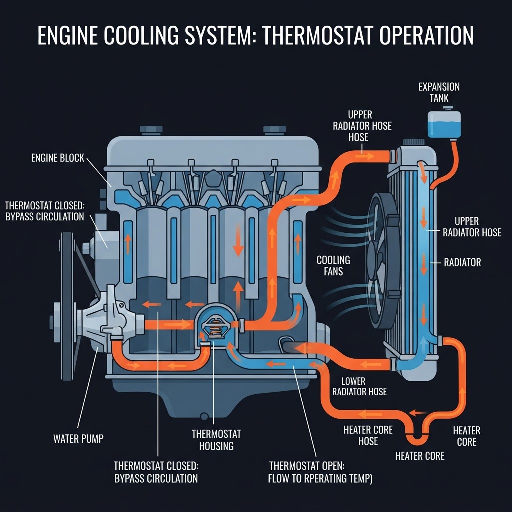
Liquid cooling (most industrial engines):
- Coolant (water/antifreeze mixture) circulates through passages in the block and head, absorbing heat from combustion
- A water pump circulates the coolant
- The thermostat regulates coolant temperature — stays closed until operating temperature is reached to allow fast warmup, then opens to route coolant through the radiator
- The radiator transfers heat from the coolant to the air
Thermostat function
A stuck-open thermostat causes the engine to run cold — poor fuel economy, increased wear, and incomplete combustion. A stuck-closed thermostat causes overheating — the most common consequence of thermostat failure.
Air cooling (smaller engines):
- Fins cast into the cylinder block and head dissipate heat directly to the airstream
- A cooling fan forces air across the fins
- Simpler than liquid cooling — no coolant, no water pump, no thermostat
- Less effective heat control — not used for large or high-output engines
EXAM TIP
Engine overheating causes warped cylinder heads, blown head gaskets, seized pistons, and crankshaft bearing damage. The sequence of investigation: coolant level, thermostat, water pump, radiator condition, and cooling fan before assuming internal engine damage.
Engine Starting Systems
Electric starting
A DC electric motor (starter motor) engages a ring gear on the flywheel to crank the engine. Powered by a battery. Most common on modern industrial engines.
Pneumatic starting
Compressed air drives a starter motor or is admitted directly to a cylinder to turn the engine. Used where electrical ignition sources are prohibited (hazardous areas) or where very high starting torque is needed (large diesel engines).
Hydraulic starting
A hydraulic motor cranks the engine using stored hydraulic pressure from an accumulator. Used in some mobile and offshore applications.
EXAM TIP
Pneumatic starting systems are used in hazardous environments because they eliminate the spark risk associated with electrical systems. This is a direct application question on the exam.
Fuel Systems
Gasoline / Natural Gas
Carburettor or fuel injection meters fuel into the intake air. Natural gas engines (common in pipeline and oilfield applications) use a gas regulator and mixer to blend fuel with intake air.
Diesel
High-pressure fuel injection delivers precisely metered fuel directly into the combustion chamber at the correct timing. Injection timing affects power, efficiency, and emissions.
Fuel filters
Critical maintenance item. Contaminated fuel plugs injectors and carburetor jets. Water in diesel fuel causes injector corrosion and microbial growth. Drain water separators regularly.
Gas Turbine Engines (Industrial)
Gas turbines as prime movers are covered in the dedicated Turbines Guide. Key distinguishing features from a prime mover selection standpoint:
- Very high power-to-weight ratio — large power output from a compact package
- High rotational speed — requires reduction gearing for most driven equipment
- Burns natural gas or liquid fuels
- High exhaust temperature — waste heat recovery possible (cogeneration)
- Used for pipeline compression, power generation, and large mechanical drives
Hydraulic Motors as Prime Movers
A hydraulic motor converts hydraulic pressure and flow into rotational mechanical output — the driven counterpart to a hydraulic pump. In a hydraulic drive system, an electric motor or engine drives a hydraulic pump, and the hydraulic motor at the other end of the circuit provides the mechanical output.
Types:
Gear motor
Simple, low cost, fixed displacement
Vane motor
Moderate pressure, smooth operation
Piston motor
High pressure, high efficiency, variable displacement available
Advantages of hydraulic drive:
- Power can be transmitted over long distances through hoses and pipes
- Speed is infinitely variable by controlling flow
- High torque at zero speed — no stall condition
- Can be reversed smoothly
- Overload protection built in (relief valve)
Applications
Mobile equipment, winches, conveyors in explosive environments (no electrical prime mover at the point of use), marine deck equipment.
EXAM TIP
A hydraulic motor and a hydraulic pump are often the same physical design operating in reverse — hydraulic fluid in drives shaft rotation out (motor), shaft rotation in drives fluid out (pump). This reversibility is why some hydraulic drives can operate in both directions and regenerate energy during braking.
Prime Mover Selection
The Red Seal exam may test prime mover selection for a given application. Key selection factors:
| Factor | Consideration |
|---|---|
| Power requirement | kW or hp output needed at the shaft |
| Speed requirement | RPM at the driven equipment |
| Duty cycle | Continuous, intermittent, or variable load |
| Location | Access to electricity, fuel type available |
| Environment | Hazardous area, outdoor/indoor, temperature extremes |
| Starting torque | Some loads require high torque at startup |
| Speed control | Fixed speed, variable speed, or precise control needed |
| Maintenance capability | Complexity of maintenance the site can support |
General rules:
Key Points for the Exam
Sample Exam-Style Questions
Work through these exam-style scenarios. Tap each to reveal the approach.
During the compression stroke of a diesel engine, only air is compressed — no fuel is present. Why, and how does ignition occur?
An engine is found to have insufficient valve clearance on the exhaust valves. What are the likely consequences if this is not corrected?
An industrial facility needs to drive a large compressor in a Class 1 Division 1 hazardous area where flammable gases may be present. Why would a pneumatic starting system be specified over an electric starting system?
A four-stroke engine has a camshaft that turns at half the speed of the crankshaft. Why?
A hydraulic motor is driving a conveyor. The motor is running but the conveyor has no torque — it stops when any load is applied. What is the most likely cause?
An engine is overheating. Coolant level is correct. List the remaining components to inspect in order of likelihood.
Frequently Asked Questions
Ready to Test Your Prime Mover Knowledge?
Prime mover questions on the Red Seal exam test both theoretical knowledge and practical application — understanding why a component works a certain way is as important as knowing what it does.
Related guides:
Last updated: September 2026 · MW Red Seal Millwright Prep is built by a millwright, for millwrights. Content is aligned with the National Occupational Analysis (NOA) for Industrial Mechanic (Millwright) — the same document that structures the Red Seal exam.